![]()
Needed Supplies:
Needed Tools:
Total time for project:
Approximately 45 minutes
DT400 Digitrax DCC throttle
SPST toggle switch Radio Shack #275-0624 or similar swtich
2 lengths of 10 inch, 22 or 24 gauge Wire
Heat shrink tubing for small gauge wire
13/64" drill bit
Hobby Saw
Soldering Iron
Solder
Flux
Standard Hobby tools such as Phillips head screw driver, wire cutters
| 1. Remove the battery cover and remove the 9V battery. Use a Phillips head screw driver and unscrew the 2 screws at the bottom corners of the throttle. | 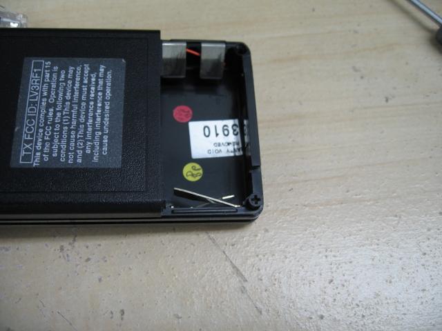 |
| 2. Slide the front of the throttle down from the back of the throttle. It should only move about half an inch. The front of the throttle is secured using a slide locking clip shown here. | 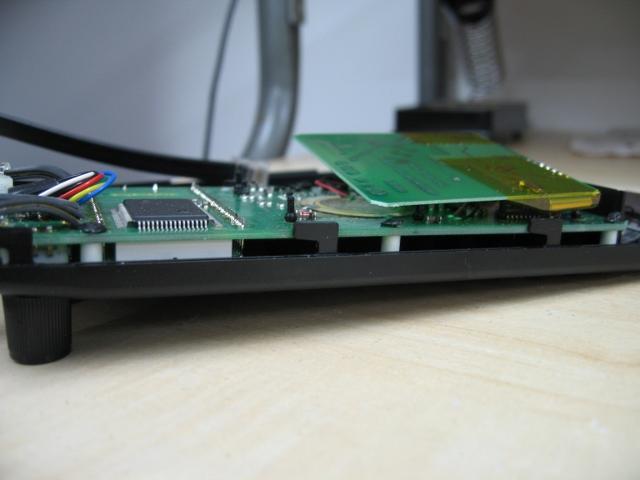 |
| 3. Pull the two halves of the throttle apart from each other. You should be able to do this using your muscles and finger nails. | |
| 4. Photo 3 shows what a DT400R looks like on the inside. | 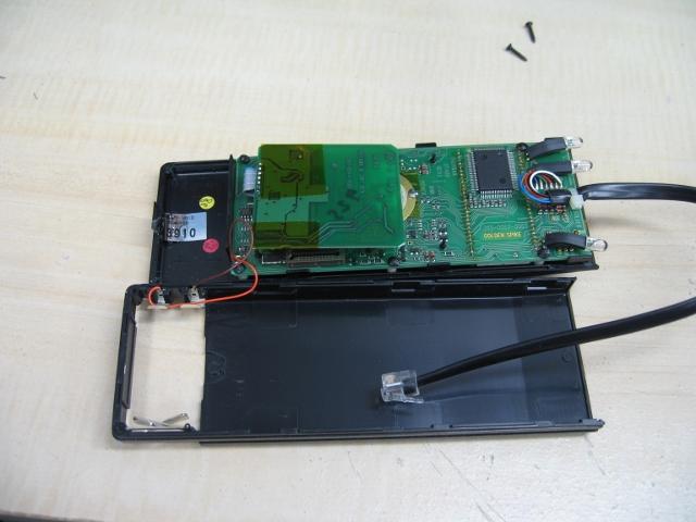 |
| 5. Solder a length of 24g wire to each of the terminals on your SPST switch. | 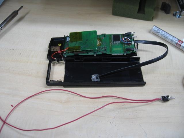 |
| 6. Test the continuity of the toggle switch using a multi meter. | 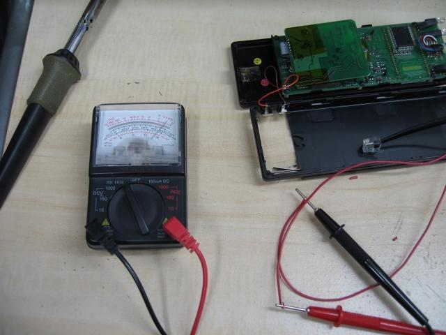 |
| 7. Unsolder the orange wire (+) from the contact tab. | 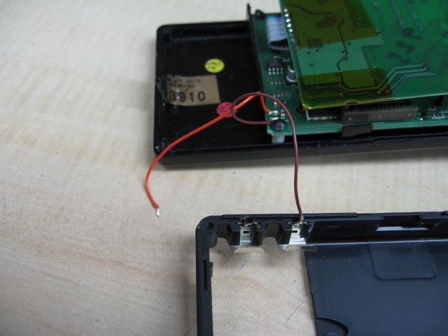 |
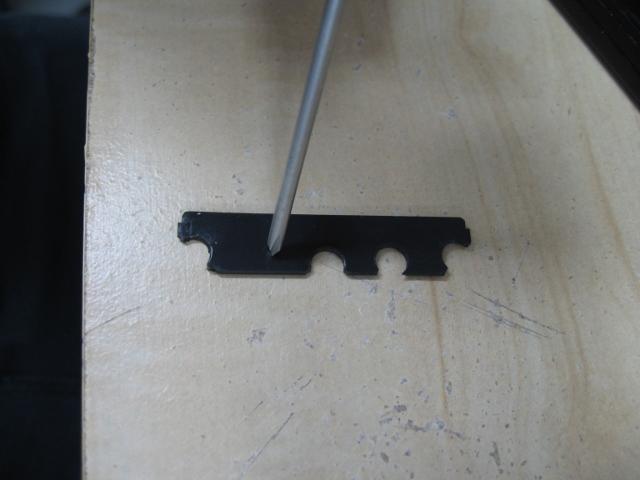
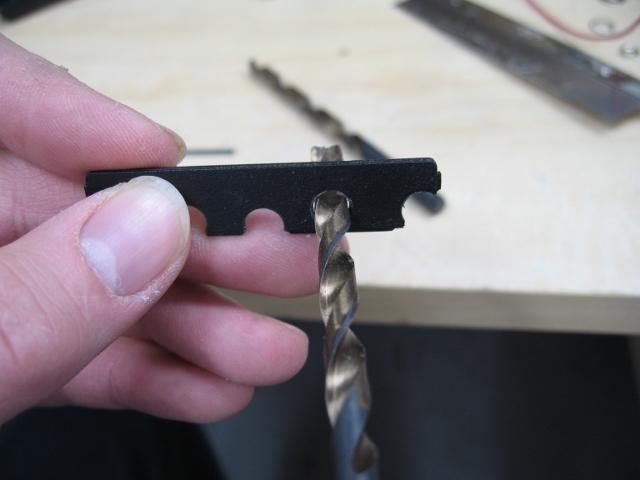
| 8. Drill a hole in the mounting plastic that is at the top of the throttle. This will wind up being a notch as opposed to a solid hole. I suggest making the center of the hole half the diameter (radius) of the drill bit from the edge of the plastic. As you'll see, I used too big of a drill bit for my install. Use the pictures as a guide to my method but do not use the measurements you see on my ruler. See photos 7,8, 9 and 10. Photo 11 is what it should look like when you are done. | 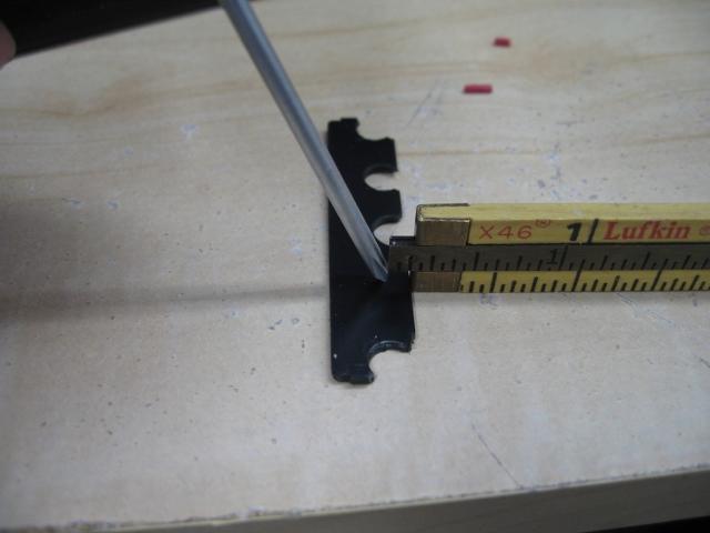 |
 | |
 | |
| 9. Use a small hobby saw to clean up the notch you have made. At this point it becomes a game of trial and error to get a good fit. Use your hobby saw to widen the notch and your drill to wobble out the hole if needed. | 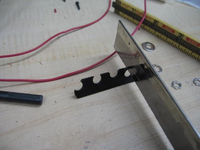 |
| 10. Test fit your toggle switch. Make sure there is enough clearance for the back of the throttle to slide on again. | 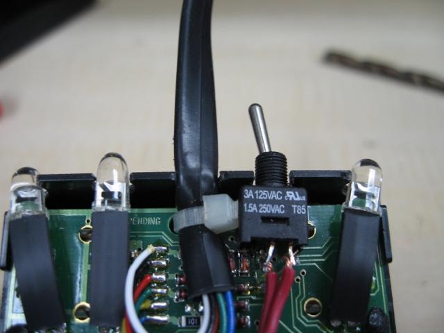 |
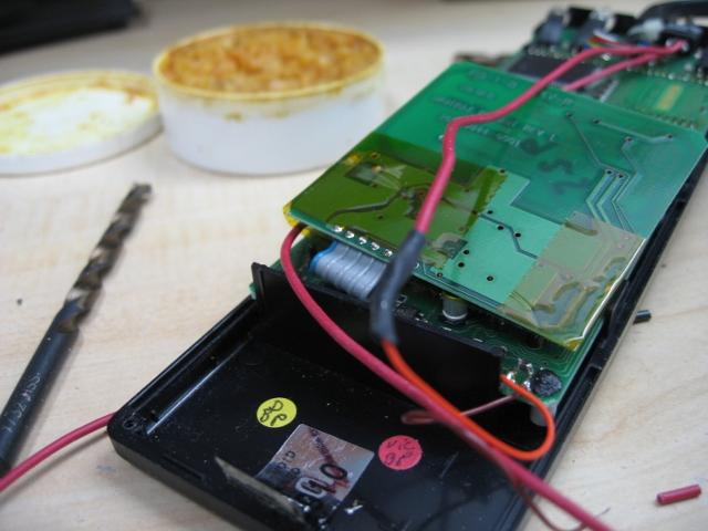
| 11. Route the wires from the switch down towards the battery compartment. I routed the wires down and to the left to avoid some components of the throttle. Trim the wire if needed. | 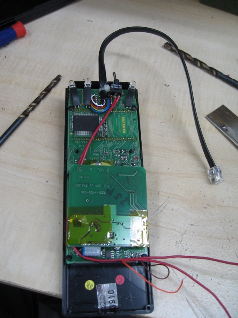 |
| 12. Slip a short section of heat shrink tubing over the red wire and push it out of the way. | |
| 13. Solder one of the wires to the loose end of the orange battery wire. Then cover the connection with the piece of heat shrink tubing and then heat it to seal it. | 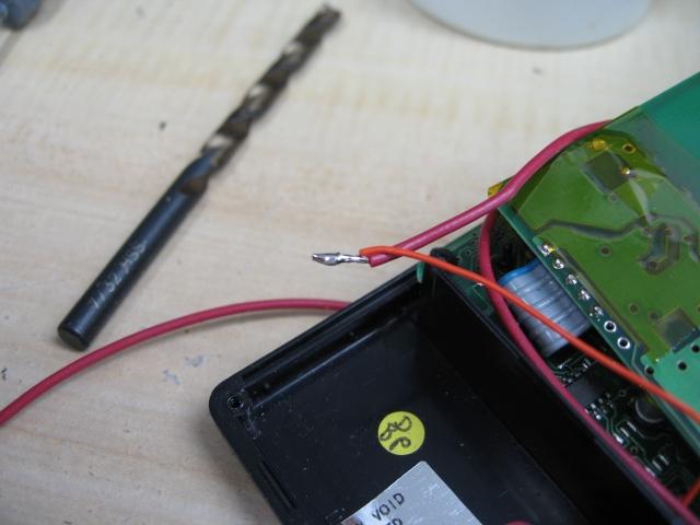 |
 | |
| 14. Solder the other red wire to the battery contact tab. | 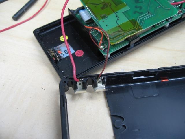 |
| 15. Place the battery against the contact tabs and make sure your switch works. | 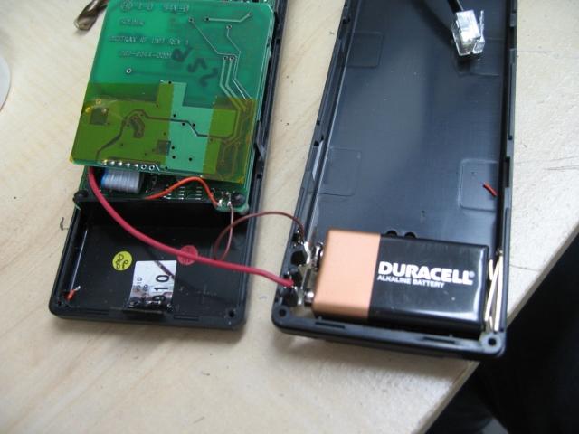 |
| 16. Re assemble the throttle by sliding the back of the throttle onto the front and at the same time holding the top mounting piece in place. Do all of this carefully to make sure the throttle clips back together without damaging the throttle. This was actually the most time consuming step in the whole process. | |
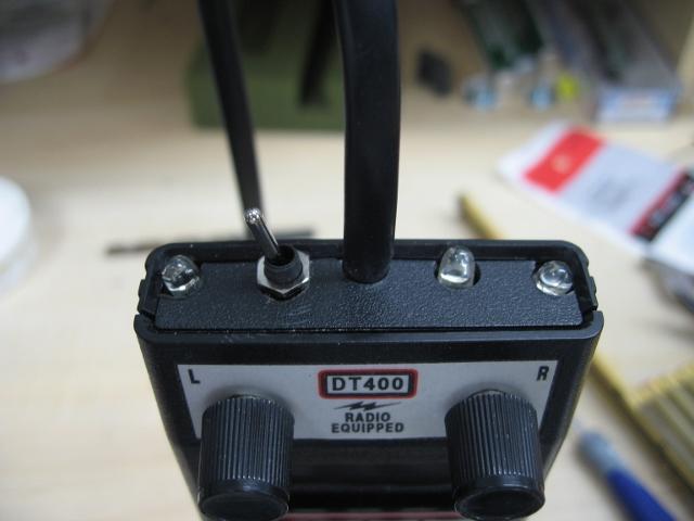
| 17. Figures 18 and 19 show the finished product. | |
 |
![]()