![]()
Yard Track Power Control Box for DCC
All photos by Glenn Koproske May 13, 2003
![]()
Yard Track Power Control Box for DCC
All photos by Glenn Koproske May 13, 2003
When we ran DCC for the first time, we found that we could not acquire our locomotives that were sitting on our club yard tracks while the Peco power routing Insulfrog switches were thrown for the main line. It was an inconvenient process to:
We decided that some sort of toggle switch arrangement was needed to bypass the Insulfrogs and supply the DCC signal to all yard tracks branching off a given N-Trak main line. That is, if the Red line is DCC, then all yard tracks branching off Red would also receive the DCC signal. Red, Yellow and Blue would be controlled independently. The toggle switch would be thrown to connect the bus line to the yard track feeder wires on the other side of the Insulfrogs. Throw the toggle switch the other way, and everything is disconnected, and power routing is returned to regular power routing operations.
At first we though we could construct this with just one toggle switch per main line, but it turns out that all the + and - wires from each track would have to join at one spot at the solder lugs on the toggle switch. This would defeat power routing for DC/analog operations. We also thought that the ideal toggle would be DPST, but these were almost impossible to find. They existed only as appliance motor switches at almost 5 bucks apiece at Lowe's. We ended up using DPDT miniature toggles, and one side of the toggle would not be wired. Since we had 10 yard tracks, we needed 10 of these. It took trips to 3 Radio Shack stores to buy that many. A plastic electrical box with a plain flat cover would hold the project and fasten underneath the throat module on one end of the yard . These toggles would have to be thrown only once per train show, so there was no need to have ready access to the box.
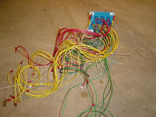
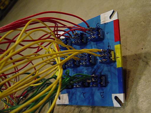
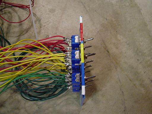
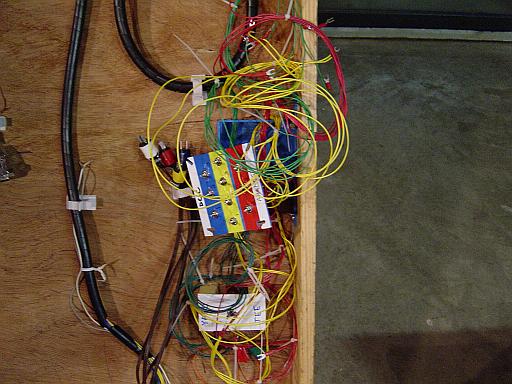
The succession of pictures below show the wired toggle switch plate right after all the soldering was done and all the spade lugs were applied. Each toggle switch has 4 independent wires on the back. The +/- main line bus wires go on the center set of lugs. The +/- feeder wires to the yard tracks connect to one outer set of lugs. The other outer set of lugs remain unconnected. Care has to be taken to number each toggle, write down the + and - sides, and make sure they are all oriented in the same direction. Red, yellow, and blue tape was applied to the cover plate. The toggles were lined up in rows on these taped areas.
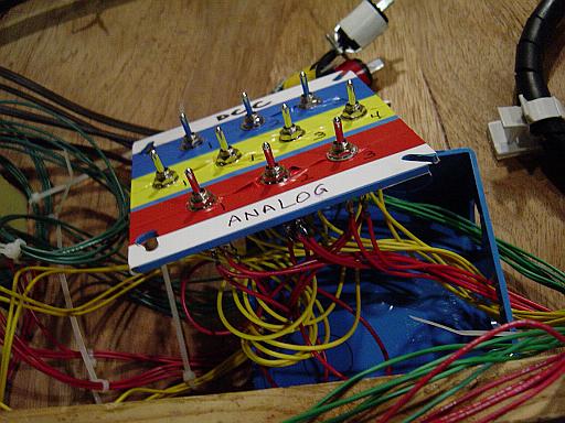
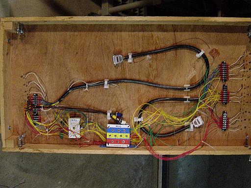
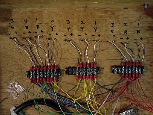
There is nothing more efficient than to use barrier terminal strips with screw-down lugs to do wiring. The last photo shows one end of the module, where the feeder wires come down from the tracks. It was very easy to tap into these same connections using wires with spade lugs. You can also see how each wire is labelled for which track it is, and +/-. It is also very much worth the trouble to buy colored hook-up wire. You might remember what your wiring scheme is today, but how is somebody else going to figure it out at a show a year from now, crawling in the dark underneath a module? You'll have to excuse the green wire, I ran out of blue.
![]()